Finger Magnetic Tactile Sensor Introduction
简体中文 | English
0. Document Information
- Document version
- v1.0
- Applicable product
- Finger Magnetic Tactile Sensor V1
1. Product Overview
Finger Magnetic Tactile Sensor V1 is a three-dimensional magnetic tactile sensor designed for robotic fingers, grippers, and flexible contact surfaces. It uses three-axis Hall magnetic-field sensing to detect magnetic-field changes caused by deformation of the elastic tactile layer and can be used to estimate normal force and tangential force in two directions.
The product uses a 3.3 V low-voltage supply and I2C communication. It is suitable for space-constrained robot end effectors that require contact detection and three-dimensional force feedback. The effective tactile area is 171 mm², the normal-force range is 0–25 N, and the tangential-force range is −10 to +10 N per axis.
1.1 Main Functions
The sensor samples and reads multidimensional tactile signals generated during contact and manipulation. Combined with magnetic tactile sensing hardware and multidimensional tactile algorithms, it provides information about contact state, force direction, force magnitude, and changing trends, and can support analysis of local surface features. Robots can use this information for contact detection, grip-force adjustment, slip-trend detection, and compliant manipulation.
1.2 Key Features
- Three-axis Hall magnetic-field sensing with Bx, By, and Bz outputs.
- Three-dimensional tactile measurement supporting normal force Fz and tangential forces Fx and Fy.
- 171 mm² effective tactile area for integration with robotic fingers and grippers.
- 60–120 Hz output frame rate for grasping, contact detection, and low-speed manipulation feedback.
- 3.0–3.6 V supply; the current specification lists a typical operating current of 40 mA.
- 200% safe overload and a design life of three million cycles.
1.3 Typical Applications
| Application | Supported Functions |
|---|---|
| Robotic dexterous hands/grippers | Contact detection, grip-force control, slip-trend detection, object interaction |
| Automated assembly | Insertion contact detection, press-fit force monitoring, compliant operation |
| Service robots | Safe touch, human-robot interaction, flexible grasping |
| Research and education | Three-dimensional tactile algorithms, force estimation, robotic perception experiments |
2. Product Components and Operating Principle
2.1 Product Appearance
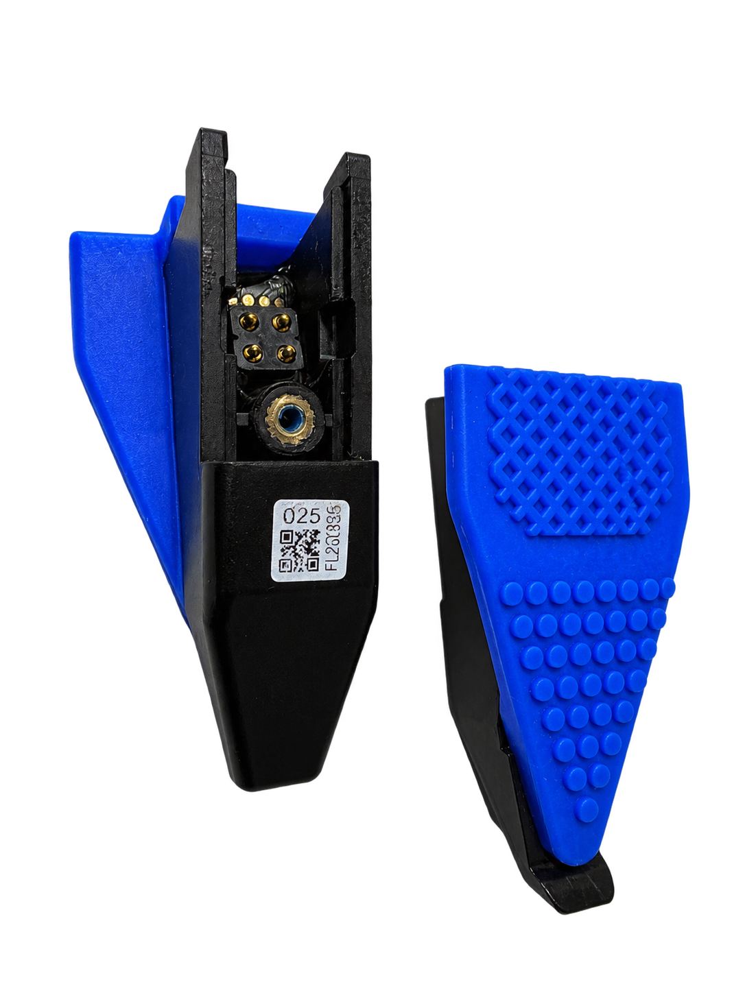
The Finger magnetic tactile sensor module consists of mechanical, magnetic, sensing, and signal-processing elements related to contact sensing. These elements work together to convert external load into magnetic-field signals. The available output data and processing location are subject to the official firmware protocol and supporting algorithm documentation for this model.
| Component | Main Function |
|---|---|
| Tactile surface | Receives external contact loads and transfers them to the internal elastic structure |
| Elastic structure | Deforms under contact load and changes the relative position between the magnetic and Hall sensing elements |
| Magnetic element | Moves with the elastic structure so the magnetic-field distribution at the sensing location changes with contact state |
| Three-axis Hall sensing elements | Measure magnetic-field components in three spatial directions and produce Bx, By, and Bz data |
| Signal-processing and communication circuit | Acquires, processes, and transmits sensor signals according to the hardware and firmware design |
| Mounting structure | Secures the module and provides a load-transfer path |
The product image is provided for product and tactile-surface identification only. It does not define internal dimensions or assembly tolerances. Mounting holes, the effective tactile region, connector location, cable direction, and mechanical datums are subject to the official Finger V1 2D drawing.
2.2 Operating Principle
- Load transfer and elastic deformation: When an external object contacts the tactile surface, the load is transferred through the surface structure to the internal elastic layer. The layer deforms according to the load position, direction, and magnitude, then gradually recovers after the load is removed.
- Conversion of deformation into magnetic-field changes: The elastic structure moves or rotates the magnetic element relative to the three-axis Hall sensing elements. Deformation in different directions produces different combinations of Bx, By, and Bz responses.
- Magnetic-field acquisition and data output: The Hall sensing elements measure the three-axis magnetic field. The signal-processing and communication circuit acquires, processes, and transmits the data according to the firmware definition.
- Calibration mapping and tactile information: With valid calibration parameters and algorithms, magnetic responses or derived deformation features can be mapped to contact state and three-axis force estimates.
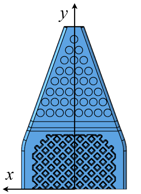
2.3 Coordinate System
| Axis | Recommended Definition | Positive Direction |
|---|---|---|
| X | First tangential axis of the tactile surface | See the Finger coordinate convention |
| Y | Second tangential axis of the tactile surface | See the Finger coordinate convention |
| Z | Normal axis perpendicular to the tactile surface | Right-hand rule; compression is positive |
3. Technical Specifications
3.1 Core Performance
| Specification | Value | Notes |
|---|---|---|
| Sensor type | Three-axis Hall magnetic-field sensing | |
| Measurement output | Bx, By, Bz | |
| Normal-force range | Fz: 0–25 N | Single-axis range |
| Tangential-force range | Fx, Fy: −10 to +10 N each | Single-axis range |
| Safe overload | 200% | |
| Effective tactile area | 171 mm² | |
| Output frame rate | 60 Hz | |
| Minimum detectable force | 0.05 N | |
| Repeatability | ≤2%FS | |
| Service life | 3 million cycles |
3.2 Electrical Specifications
| Item | Minimum | Typical | Maximum | Notes |
|---|---|---|---|---|
| Supply voltage | 3.0 V | 3.3 V | 3.6 V | Do not apply more than 5 V |
| Operating current | — | 40 mA | — | |
| Interface protocol | — | I2C | — | |
| I/O logic level | — | 3.3 V domain | — |
3.3 Environmental Specifications
The currently documented operating-temperature range is 0–50 °C. If the application involves rapid temperature changes, monitor zero drift, stabilization time, and force-estimation changes rather than checking communication alone.
Storage temperature, humidity, condensation, dust, liquid exposure, vibration, and ingress-protection ratings have not been fully confirmed. Until formal ratings are available, do not describe the product as waterproof, dustproof, or suitable for condensing environments. Confirm material compatibility and protection requirements with the product team before cleaning or use in special environments.
During product selection or acceptance testing, record temperature, humidity, mounting orientation, preload, and magnetic interference sources. Motors, magnets, and high-current conductors near magnetic sensors may affect raw magnetic-field readings; verify the actual installation to determine whether isolation, shielding, or baseline compensation is required.
| Item | Value | Notes |
|---|---|---|
| Operating temperature | 0–50 °C | Avoid rapid temperature changes |
| Storage temperature | 10–35 °C | To be released after high/low-temperature storage validation |
| Operating humidity | 10%RH–80%RH | The product has no declared waterproof rating |
| Ingress protection | Not defined | Do not use directly in liquid, dust, or corrosive environments |
4. Mechanical Installation
4.1 Pre-installation Inspection
- Check the tactile surface for damage, warping, contamination, or permanent deformation.
- Check cables, solder joints, and connectors for looseness or damage.
- Make sure the mounting structure will not pinch the circuit, cable, or effective tactile area.
- Verify the supply voltage and host I/O level. Do not connect or disconnect while powered.
4.2 Installation Principles
Recommended installation sequence
Confirm the mounting datum and effective tactile area, then secure the module while power is disconnected. Route the cable and verify its motion range. Make sure the tactile surface is not compressed by the enclosure, adhesive layer, or fasteners before applying power. For the first assembly, record the mounting orientation, fastening method, fasteners, and cable routing with photographs to support calibration reproduction and troubleshooting.
Load path and preload
The mounting structure should transfer external contact loads through the tactile surface to the sensing structure. Enclosure edges, screw heads, and adhesive layers must not create bypass supports. Avoid uneven clamping, bending, twisting, and assembly preload.
Operating restrictions
Applying force outside the effective tactile area, pressing with sharp tools, prying from the edge, or repeatedly peeling the adhesive layer may cause localized damage.
Post-installation inspection
- The mounting datum must be flat, and the secured sensor body must not be distorted by preload.
- Leave deformation clearance around the tactile surface; the enclosure and fasteners must not restrict it.
- Apply external force primarily within the effective tactile area. Avoid puncturing, scratching, and edge prying.
- Provide cable strain relief so robot motion does not repeatedly pull the connector.
- Perform a zero check after installation. Reinstall or recalibrate if the no-load output is significantly offset.
4.3 Mechanical Drawing Status
Overall dimensions, mounting-hole locations, datums, fastener specifications, recommended torque, connector orientation, and cable bend clearance must be defined by a controlled Finger V1 mechanical drawing. The 171 mm² effective tactile area is the currently documented value; the formal drawing must also define its boundary and position relative to the mounting datums.
The product manual, 2D drawing, 3D model, and assembly instructions must use the same hardware version. Changes to the tactile layer, support structure, or mounting interface require new zero, direction, and range checks.
| Drawing Item | Formal Release Requirement |
|---|---|
| Overall dimensions | Length, width, height, and maximum envelope dimensions |
| Mounting interface | Hole locations, threaded/through-hole specifications, datums, and fastening torque |
| Effective area | Geometric boundary and center of the 171 mm² region |
| Connector | Model, pin-1 orientation, mating clearance, and cable bend radius |
| Tolerances | Locating-hole tolerances, general tolerances, and assembly clearances |
5. Electrical Connection
5.1 Power Requirements
- Use a stable 3.3 V DC supply. The normal supply range is 3.0–3.6 V.
- Overcurrent and reverse-polarity protection are recommended. Check voltage and polarity before power-on.
- The sensor and host controller must share a reliable common ground.
- Do not share a high-impedance supply path with motors, relays, or high-current switching circuits.
- The current specification lists 40 mA; reserve margin until the maximum current is formally confirmed.
5.2 Pin Definition
| Pin | Signal | Direction | Description |
|---|---|---|---|
| To be confirmed | VDD | Input | 3.3 V supply; permitted range 3.0–3.6 V |
| To be confirmed | GND | — | Power and signal reference ground |
| To be confirmed | SCL | Input | I2C clock, open-drain |
| To be confirmed | SDA | Bidirectional | I2C data, open-drain |
Prohibited Action
Do not wire the product based only on cable color or another model's manual before the formal pinout is released. Incorrect power wiring or applying a 5 V signal may cause permanent damage.
5.3 Recommended Wiring Practices
- Pull SDA and SCL up to a 3.3 V supply compatible with the sensor I/O.
- Select pull-up resistance based on total bus capacitance and speed; the formal recommended value requires hardware validation.
- For long cables or strong interference, reduce the communication rate and use ground pairing, shielding, or filtering.
- When multiple devices share one bus, make sure their addresses do not conflict.
6. I2C Communication
6.1 Interface Parameters
| Item | Current Definition |
|---|---|
| Physical interface | I2C, two-wire open-drain bus with external pull-ups |
| Supply domain | 3.3 V |
| Slave address | 7-bit address; left hand 0x5E, right hand 0x5F |
| Maximum bus speed | 1 Mbps |
| Output frame rate | 60 Hz |
| Byte order | Little-endian |
| Frame check | CRC32 / IEEE 802.3, little-endian |
| Read transaction length | The slave always sends 272 bytes; calculate the valid frame length from the header length and ignore trailing bytes |
| Maximum write transaction | 280 bytes (slave receive-buffer limit) |
6.2 Communication Transaction
The sensor uses a write-request-then-read-response transaction. The host writes a complete request frame to the slave address. The slave parses the request and generates a response in an internal task, after which the host reads the response. The response is not generated immediately at the end of the write transaction, so reading immediately may return the previous response.
- Write a complete request frame using main protocol
0x0011and subprotocol0x0000; the PDU may be empty. - Wait at least 1–2 ms for the slave to assemble the response.
- Read the response. The slave sends 272 bytes for each read transaction; the host may terminate early with NACK/STOP.
- Calculate the valid frame length from the header
length. Bytes after the valid frame are not protocol data.
The slave transmit buffer is not cleared automatically after transmission, so the same response can be read repeatedly. Use the response packet sequence number to determine whether the data is new; do not assume each read is a new sample.
6.3 Frame Format
Requests and responses use the same frame structure. All multibyte integer fields are little-endian.
| Offset | Field | Length | Description |
|---|---|---|---|
| 0 | magic | 1 | Fixed value 0xA5 |
| 1 | SrcID | 1 | Fixed to 0x00 for host requests |
| 2 | DstID | 1 | Slave address 0x5E or 0x5F |
| 3 | length | 2 | PDU length, little-endian; excludes padding and CRC |
| 5 | protocolID | 2 | Main protocol, little-endian; sensor data uses 0x0011 |
| 7 | SubProtocolID | 2 | Subprotocol, little-endian; sensor data uses 0x0000 |
| 9 | PDU | N | Payload; may be empty for a sensor-data request |
| 9+N | padding | 0–7 | 0x00 padding to align the full frame to 8 bytes |
| Final 4 bytes | CRC32 | 4 | IEEE CRC-32, little-endian, covering magic through the final padding byte |
Padding and total frame length
no_pad_len  = 9 + pdu_len + 4
padding_len = (8 - (no_pad_len % 8)) % 8
total_len   = no_pad_len + padding_len
A sensor-data request has a zero-length PDU, three padding bytes, and a valid total length of 16 bytes. A response has a 147-byte PDU, no padding, and a valid total length of 160 bytes.
Request examples (read sensor data)
Left hand (0x5E):  A5 00 5E 00 00 11 00 00 00 00 00 00 E6 24 F4 FD
Right hand (0x5F): A5 00 5F 00 00 11 00 00 00 00 00 00 D8 4F 36 12
6.4 Sensor Data Response (0x0011 / 0x0000)
The response PDU is fixed at 147 bytes and the complete valid frame is 160 bytes. The first part of the PDU is an image of 49 int16 holding registers, followed by a packet sequence number, timestamp, and reserved area.
| PDU Offset | Length | Type | Content |
|---|---|---|---|
| 0–89 | 90 | 45 × int16 | 15 Hall channels, three axes each: Bx, By, Bz |
| 90–95 | 6 | 3 × int16 | Reserved; currently fixed to 0 |
| 96–97 | 2 | int16 | Temperature value converted by firmware |
| 98–101 | 4 | uint32 | Response packet sequence number, little-endian |
| 102–105 | 4 | uint32 | Sensor snapshot time in ms, little-endian |
| 106–146 | 41 | uint8[41] | Reserved; currently all 0x00 |
Parsing
value[i]      = int16_le(PDU[2*i], PDU[2*i+1])
Bx(n)         = value[3*n + 0]        // n = 0..14
By(n)         = value[3*n + 1]
Bz(n)         = value[3*n + 2]
temperature   = value[48]
packet_seq    = uint32_le(PDU[98..101])
timestamp_ms  = uint32_le(PDU[102..105])
Channel n corresponds to Hall sensing point n on the tactile surface. The mechanical drawing defines each point's physical location, coordinate direction, and mounting relationship. The firmware applies coordinate transforms for each point's mounting orientation before output.
- The packet sequence number starts at 0 after reset and increments for each valid
0x0011/0x0000request. It wraps to 0 after0xFFFFFFFF. - Re-reading the same response without sending a new request does not change the sequence number, which allows duplicate frames to be detected.
- The timestamp is captured when the sensor snapshot is generated, not when the request arrives or the response is sent.
- The timestamp wraps approximately every 49.7 days. Use unsigned subtraction when calculating time differences.
6.5 Power-on and Read Sequence
| Step | Host Operation | Acceptance Criterion |
|---|---|---|
| 1 | Keep SDA/SCL released in open-drain state and apply 3.3 V | Stable voltage with no abnormal current |
| 2 | Wait for initialization; firmware takes approximately 400 ms to initialize I2C and Hall devices | The device acknowledges 0x5E / 0x5F |
| 3 | Write the 16-byte 0x0011/0x0000 request frame | The slave acknowledges its address |
| 4 | Wait at least 1–2 ms, then read the response | A frame with magic equal to 0xA5 is received |
| 5 | Verify SrcID, DstID, protocolID, SubProtocolID, and CRC32 | Fields match and CRC is valid |
| 6 | Calculate the valid frame length from length and ignore trailing bytes | Valid length is 160 bytes |
| 7 | Compare the packet sequence number to confirm a new frame | Sequence number increments from the previous frame |
| 8 | Capture several no-load frames to establish or check the zero baseline | Output is stable within the permitted zero range |
| 9 | Read periodically at the application rate, sending a new request for each frame | Rate does not exceed the firmware output rate |
At power-on, the firmware automatically captures a baseline and requires several consecutive stable frames. Wait at least 1 second after power-on, then confirm that the packet sequence number increments and all axes are stable under no load before using the data.
6.6 Integration Notes
- The slave sends 272 bytes for every read transaction. Bytes after the valid frame may be zero or stale buffer contents; truncate according to
lengthand discard the remainder. - The slave does not automatically clear a response after transmission. Repeated reads return the same frame and sequence number.
- The current firmware does not validate request-frame
lengthor CRC32, but the host must still send a complete request with a correct CRC for future firmware compatibility. - Read the response for one request before sending the next. Rapid consecutive writes may overwrite an unprocessed request.
- Implement timeout and retry handling for missing acknowledgements, CRC errors, invalid frame lengths, and sequence numbers that do not change. Do not treat stale frames as current measurements.
- Validate pull-up resistance, bus capacitance, and speed for the actual cable length. Reduce the speed for long cables or high-interference environments.
7. Data Definition and Calibration
7.1 Raw Magnetic-field Data
Bx, By, and Bz are the three magnetic-field components measured by the three-axis Hall devices. The formal protocol must define bit width, signed representation, units, zero offset, full scale, and temperature compensation.
7.2 Force Data
| Data | Range | Unit | Description |
|---|---|---|---|
| Fx | −10 to +10 | N | Tangential force along X; see the Finger coordinate convention |
| Fy | −10 to +10 | N | Tangential force along Y; see the Finger coordinate convention |
| Fz | 0 to 25 | N | Normal force; see the Finger coordinate convention |
7.3 Zeroing and Calibration Recommendations
- Make sure the tactile surface is completely unloaded and the mounting state is stable before zeroing.
- Zeroing estimates the current unloaded baseline; calibration maps sensor signals to reference forces.
- Wait for temperature and output to stabilize after power-on before capturing zero samples.
- Use a multi-frame average for the zero value. The algorithm team should define the frame count and tolerance threshold.
- Recalibrate after replacing the tactile surface, reinstalling the sensor, an overload event, or a large temperature change.
- If raw Bx/By/Bz values are output, the force model must be bound to the specific sensor or its calibration parameters.
7.4 Data Quality Assessment
For every frame, check communication success, field length, checksum, status, numeric validity, timestamp/frame-counter continuity, and whether each axis is within range.
Mark over-range data and frames with failed checksums as invalid and stop using them according to the application safety policy. Upper layers may filter or estimate briefly, but they must retain the original status flags. For persistent faults, inspect power, grounding, wiring, mounting preload, magnetic interference, and tactile-layer condition, and record the reproduction conditions.
Integration logs should include timestamps, raw communication frames, decoded Bx/By/Bz or Fx/Fy/Fz values, status/check results, supply voltage, temperature, mounting version, firmware version, and reference load.
| Symptom | Possible Cause | Recommended Action |
|---|---|---|
| No-load offset keeps increasing | Mounting preload, thermal drift, permanent structural deformation | Remove the load, reinstall, and zero; stop using the sensor if the fault remains |
| Data jumps or frames are lost | Bus interference, unsuitable pull-up, supply fluctuation | Check waveforms, grounding, cable length, and power decoupling |
| One axis saturates | Load exceeds range or coordinate direction is incorrect | Remove load immediately; check load point and data format |
| Repeatability decreases | Tactile-surface wear, looseness, or contamination | Clean and inspect the structure; replace the tactile layer if necessary |
8. Operating Procedure
8.1 First Use
- Verify the product model, appearance, connector, and packaging condition.
- Complete mechanical installation and I2C wiring with power disconnected.
- Check 3.3 V supply polarity, SDA/SCL levels, and common grounding.
- Apply power and confirm there is no abnormal current.
- Perform an I2C scan or read the identification register after the protocol is released.
- Capture data with no load and complete zeroing/calibration.
- Apply load gradually and verify direction, range, and data stability.
- Add overload, communication timeout, and invalid-data handling to the host program.
8.2 Normal Operation Recommendations
- Apply loads smoothly. Avoid impact, striking, puncturing, and scratching with hard objects.
- Keep margin below the rated range for continuous operation. Do not use the safe-overload value as the working range.
- Diagnose communication timeouts, out-of-range data, abrupt changes, and sensor disconnection on the host.
- For safety-critical grasping, combine tactile data with motor current, vision, or other sensors for redundancy.
9. Precautions and Maintenance
9.1 Operating Precautions
- This product is intended for touching, grasping, and squeezing. It is not intended for puncturing, burning, striking, or other destructive scenarios.
- Do not operate continuously above the rated range. After an overload, remove the load and check zero and repeatability.
- Do not use in undeclared wet, liquid, dusty, corrosive, or strong-magnetic environments.
- Prevent electrostatic discharge from people or tools directly contacting the circuit or signal pins.
- Do not connect or disconnect while powered, reverse the supply, or apply voltage outside the logic domain to signal pins.
9.2 Cleaning
- Disconnect power and use a soft, lint-free cloth to remove dust and stains.
- If necessary, use a small amount of material-compatible neutral cleaner. Do not immerse the product.
- Do not use strong acids, strong alkalis, corrosive solvents, or hard brushes.
- Allow the product to dry completely before reapplying power and performing a zero check.
9.3 Periodic Inspection
| Inspection Item | Recommended Interval | Acceptance Criterion |
|---|---|---|
| Tactile surface and structure | Before each use | No damage, delamination, permanent deformation, or debris |
| Cable and connector | Weekly or according to usage | No looseness, breaks, wear, or pulling |
| No-load zero | At each power-on or before critical tasks | Stable and within the application's permitted range |
| Range and repeatability | During scheduled maintenance | No significant drift compared with a reference load |
10. Troubleshooting
| Symptom | Possible Cause | Recommended Action |
|---|---|---|
| No response | No power, reversed polarity, wrong address, SDA/SCL reversed | Disconnect power and check supply and wiring; verify bus waveforms and protocol version |
| Bus held low | Wiring short, device fault, incorrect host configuration | Disconnect devices one at a time; check open-drain configuration and pull-ups |
| Output always zero | Wrong register, sampling not started, missing calibration parameters | Check registers and status bits; reinitialize |
| Excessive no-load output | Mounting preload, stuck tactile layer, thermal drift, zeroing not performed | Remove the load and inspect the structure; zero again after stabilization |
| High data noise | Supply noise, long cable, interference, insufficient filtering | Improve decoupling and grounding; reduce speed; add appropriate filtering |
| Incorrect force direction | Coordinate, sign, or byte-parsing error | Verify with a known single-axis load and align coordinate definitions |
| Output does not recover after load removal | Overload or permanent structural deformation | Stop using the sensor immediately and contact technical support |
11. Storage and Transportation
- Clean and dry the product before storage. Use antistatic packaging and structural protection.
- Avoid drops, severe vibration, compression, and loading of the tactile surface during transportation.
- Do not store with strong magnets, corrosive chemicals, or items that generate large amounts of dust.
- After long-term storage, inspect appearance, zero, and basic operation before use.