DAS Gripper Controller Manual
简体中文 | English
1. Important Safety Information
1.1 Safety Instructions
Before first use, read this chapter thoroughly and follow all safety guidelines.
For assistance: support@genrobot.ai.
1.1.1 Warning Sign Meaning
- ⚠️ Danger: May cause serious injury, death, or major property damage.
- ⚠️ Warning: May cause personal injury or equipment damage.
- ⚠️ Attention: May result in device malfunction or data loss.
- 💡 Tip: Helpful suggestions for better operation.
1.2 Liability & Restrictions
- Do not modify or alter the device.
- GENROBOT.AI is not responsible for issues caused by misuse, unauthorized changes, or operational errors.
- Using this device means you agree to all safety terms and assume full responsibility for its operation.
- The product is not intended for users under 18 years old.
1.3 Integrator & User Responsibilities
- Conduct a complete threat and risk assessment before deployment.
- Implement proper security protections based on assessment results.
- Ensure all hardware and software are installed and configured correctly.
- Do not disable or change safety measures without authorization.
- Comply with relevant laws, standards, and industry regulations.
1.4 Environmental Requirements
1.4.1 Operating Conditions
- Operating temperature: 0°C–40°C
- Storage temperature: -20°C–60°C
- Humidity: 10–90% (non-condensing)
- Protection rating: IP52
1.4.2 Environmental Precautions
- Avoid strong magnetic fields and prolonged direct sunlight.
- Keep away from heat sources and corrosive environments.
- Operate in a clean, dry, and well-ventilated area.
1.5 Operational Safety
1.5.1 Pre-operation Checks
- Ensure the device has no visible damage.
- Verify all cables are intact.
- Confirm the battery is charged.
1.5.2 Operating Guidelines
- Always operate within line of sight.
- Keep all body parts away from the device’s moving range.
1.5.3 Exception Handling
- Stop operation immediately if abnormalities occur.
- Do not disassemble or repair without authorization.
- Contact technical support for assistance.
2. Product Overview
2.1 Product Introduction and Assembly
The DAS Controller is a homogeneous controller for the DAS Gripper. After users collect data and complete training with the DAS Gripper, they can deploy models with the DAS Controller.
Package List
| Item | Quantity |
|---|---|
| DAS Controller | × 1 |
| Replaceable gripper heads | × 3 |
| Type-C data cable | × 1 |
| Power cable | × 1 |
| L-shaped hex key | × 1 |
| M3 bolts | Several |
2.1.1 Structural Assembly
Gripper Assembly
Gripper assembly diagram

| Gripper Type | Use Case |
|---|---|
| Universal gripper | Suitable for most grasping tasks |
| Tactile gripper | Suitable for tasks requiring precise force control |
| Soft gripper | Provides better conformity |
Flange Assembly
The end of the DAS Controller has reserved mounting holes, and the side has three reserved M3 threaded holes. A flange component is required for assembly. The flange structural component, whose specific dimensions should refer to the corresponding 3D model, must be designed and fixed according to the mounting hole pattern of the robotic arm or other manipulator end.
When using the DAS Controller with a third-party robotic arm, install an adapter flange:
| Step | Operation |
|---|---|
| 1 | Install the flange onto the robotic arm end |
| 2 | Fix the DAS Controller to the flange with three M3 screws |
Flange installation diagram

Dimension Parameters
Controller V1

Controller V2

Controller V3
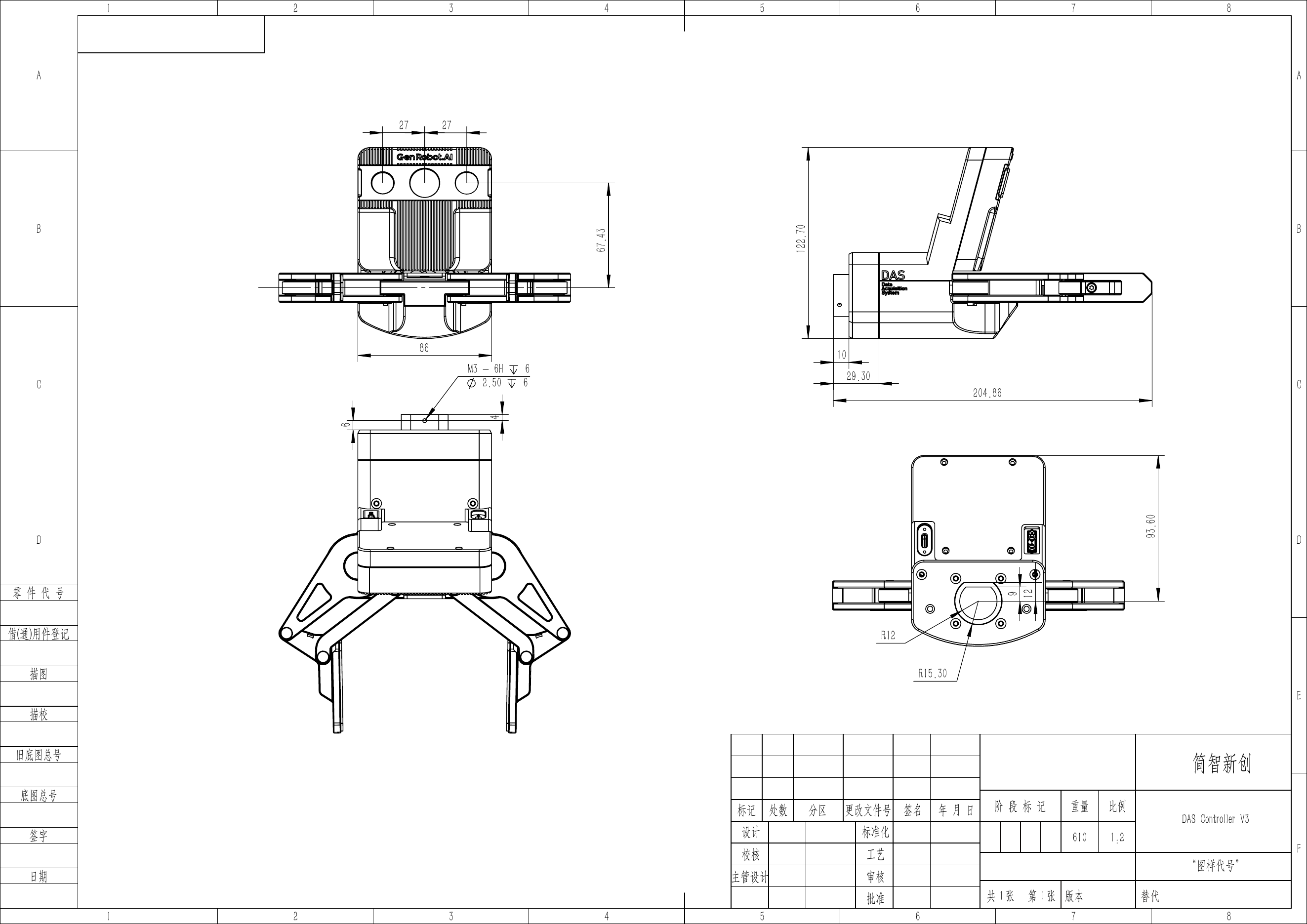
Controller V4
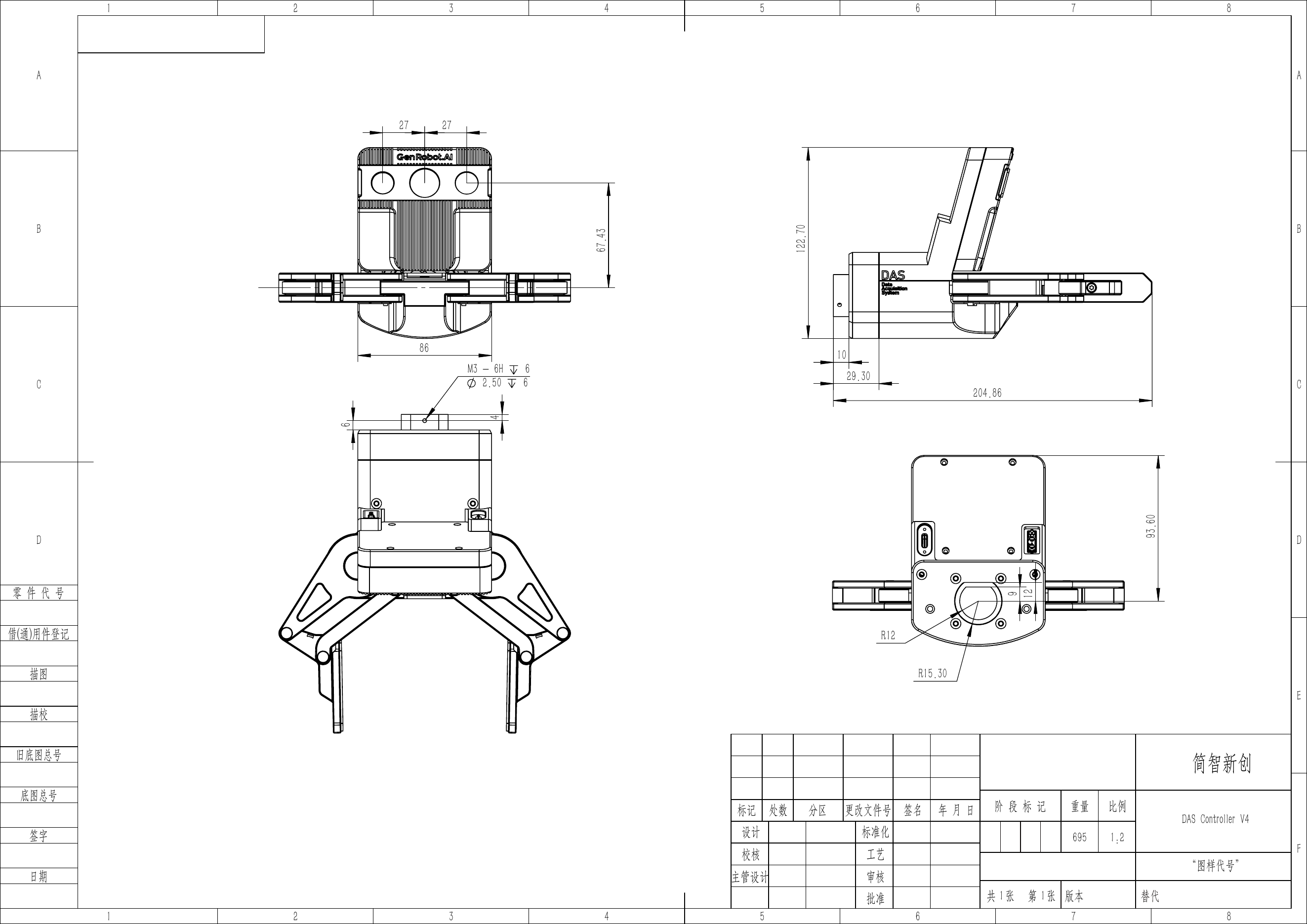
2.1.2 Electrical Connection
| Interface | Specification |
|---|---|
| Power | XT30 2+2 interface, 24V, XT30(PB) connector type |
| Communication and control | Unified Type-C interface |
Insert an XT30 series female connector into the DAS Controller XT30 2+2 interface and connect it to a 24V power supply.
2.1.3 Communication Connection
| Step | Description |
|---|---|
| 1 | Connect the Type-C cable to the Controller and connect the USB end to the PC |
| 2 | Prepare a computer and connect it to the data acquisition unit (Pika Sense) |
| Configuration | Requirement |
|---|---|
| Operating system | Linux |
2.2 SDK Usage Instructions
SDK Repositories and Computer Environment Requirements
General requirement: All SDKs require a USB 3.0 interface to connect to the Controller. For dependency installation, refer to each repository's
requirements.txtor README.
| SDK | Repository | Operating System | Runtime Environment |
|---|---|---|---|
| ROS2 SDK | gen_con_sdk_ros2_release | Ubuntu 24.04 (recommended) | ROS 2 Jazzy, Python 3.10+ |
| C++ SDK | gen_con_sdk_cplus_release | Ubuntu 20.04 (recommended) | C++17, CMake 3.16+ |
| Python SDK | gen_con_sdk_python_release | Ubuntu 20.04 (recommended) | Python 3.8+, no ROS dependency |
| ROS1 SDK | gen_controller_sdk_release | Ubuntu 20.04 (recommended) | ROS 1 Noetic, Python 3.8+ |
2.2.1 Gripper Connection Configuration
Refer to each SDK repository README to complete USB interface configuration and driver startup.
2.2.2 Camera SDK Instructions
Camera Node Function
The camera node captures image data from three cameras and publishes it to the corresponding ROS Topics, providing visual input for the gripper system.
Resolution Configuration
The system tries to configure resolutions in priority order and supports the following resolutions:
| Resolution | Description | Typical Use |
|---|---|---|
| 1600×1296 | High resolution (default) | Fine manipulation and image processing |
| 640×480 | Standard resolution | Real-time preview and low-compute scenarios |
2.2.3 Gripper SDK Instructions
The DAS Controller provides gripper control and sensor data interfaces through the ROS SDK. The following sections describe communication features and Topics. For camera Topics, see 2.2.2 Camera SDK Instructions.
Core Features
| Item | Description |
|---|---|
| Communication method | Bidirectional serial communication based on the custom DAS protocol |
| Data update frequency | Encoder and tactile sensors run at 30 Hz; up to 50 Hz when tactile gripper heads are not installed |
| Control precision | Millimeter-level distance control for fine manipulation |
| Operation modes | Supports single-gripper and dual-gripper modes |
| Safety protection | Supports emergency stop, motor disable, and other safety operations |
| Distance range | Target opening/closing distance [0.0, 0.103] m (about 0-103 mm) |
Topic List
Single-Gripper Mode - Published Topics:
| Topic Name | Message Type | Update Frequency | Description |
|---|---|---|---|
/encoder | std_msgs/Float32 | 30 Hz | Real-time encoder position (unit: m) |
/tactile/left | std_msgs/Int8MultiArray | 30 Hz | Left tactile sensor data |
/tactile/right | std_msgs/Int8MultiArray | 30 Hz | Right tactile sensor data |
Dual-Gripper Mode - Published Topics:
| Topic Name | Message Type | Update Frequency | Description |
|---|---|---|---|
/left_gripper/encoder | std_msgs/Float32 | 30 Hz | Left gripper real-time encoder position (unit: m) |
/left_gripper/tactile/left | std_msgs/Int8MultiArray | 30 Hz | Left gripper left tactile sensor data |
/left_gripper/tactile/right | std_msgs/Int8MultiArray | 30 Hz | Left gripper right tactile sensor data |
/right_gripper/encoder | std_msgs/Float32 | 30 Hz | Right gripper real-time encoder position (unit: m) |
/right_gripper/tactile/left | std_msgs/Int8MultiArray | 30 Hz | Right gripper left tactile sensor data |
/right_gripper/tactile/right | std_msgs/Int8MultiArray | 30 Hz | Right gripper right tactile sensor data |
Subscribed Topics (Control Commands):
| Topic Name | Message Type | Description |
|---|---|---|
/target_distance | std_msgs/Float32 | Single-gripper target opening/closing distance (unit: m) |
/left_gripper/target_distance | std_msgs/Float32 | Left gripper target opening/closing distance (unit: m) |
/right_gripper/target_distance | std_msgs/Float32 | Right gripper target opening/closing distance (unit: m) |